Transponders, part 3
Previously I promised to get my hands dirty, and it’s been a whole week since. I should deliver on the promise, so here’s another scribble in the series. Remember, this time we’ll try to get something working by using an off-the-chopshop component:
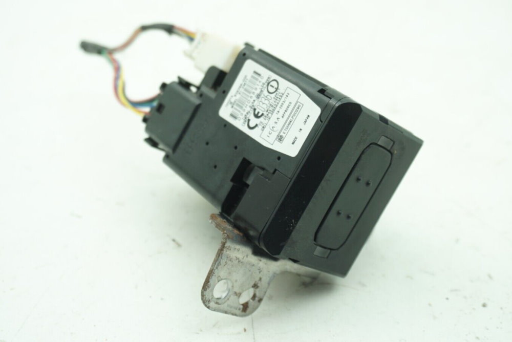
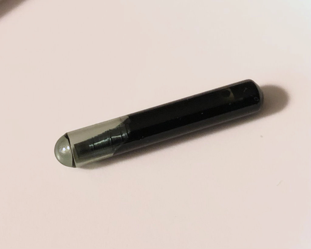
This comes from a certain brand of road vehicles and serves as a credentials receptacle to validate you are someone who is allowed to get the thing going. Simply speaking, it’s a key slot for your car key. At the time of writing this opus, these could be had for about EUR20, so well within a curious person’s budget. Skipping on the actual mechanics of plugging it in and getting it back out, I will concentrate on the topmost part visible on the photo above, the one with the label on.
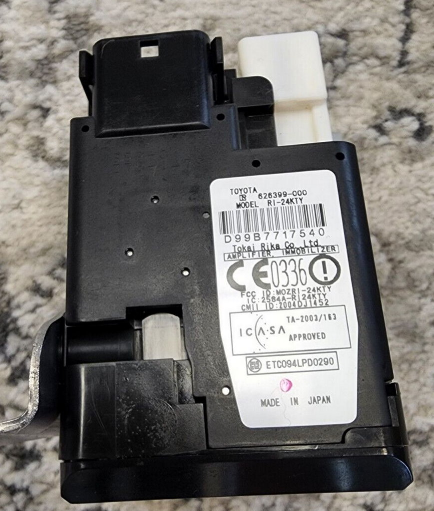
The thing we’re interested in looks like it’s an integral part of the whole key slot, but it is only held in place by two clips at the connector housing. Releasing the clips, we can get the part off. It’s not super important to do that, though, as I can tell you there’s only two important things inside: a PCB with the familiarly looking TMS3705A device and an antenna coil. All that wealth is connected to the external world like this:
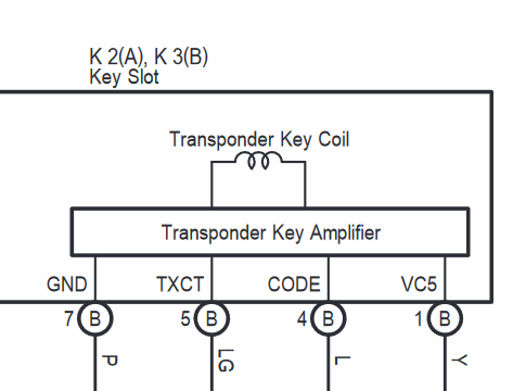
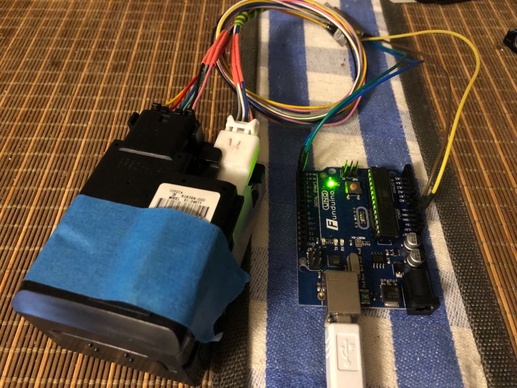
Nothing extraordinary, really. The TXCT name should already be familiar, and the CODE wire is connected to the SCIO pin. Notably, the two lines are inverted from what’s in the TMS3705 datasheet, and the SCIO line is open-collector. This actually makes our life easier as a UART unit can be used to receive data from the reader. I will be using an Arduino board, as it will readily provide the +5V required to power the device and its MCU has an UART.
Fixed-code transponders
Following the wiring diagram, I connected it like this:
| Reader pin | Signal | Arduino pin |
|---|---|---|
| 1 | +5V | 5V |
| 4 | CODE | 0 |
| 5 | TXCT | 2 |
| 7 | GND | GND |
Writing the setup code right away:
#define CODE_PIN 0
#define TXCT_PIN 2

void setup() {
  // put your setup code here, to run once:
  pinMode(TXCT_PIN, OUTPUT);
  pinMode(CODE_PIN, INPUT_PULLUP);
  Serial.begin(15625);
  Serial.println(">Ready!");
}
With that out of the way, I am ready to manipulate things further. As twiddling the TXCT pin will not be as easy, let’s just go ahead and implement all that in software.
void TMS3705_TXCT_Assert() {
  // turn the RF field ON
  digitalWrite(TXCT_PIN, HIGH);
}

void TMS3705_TXCT_Negate() {
  // turn the RF field OFF
  digitalWrite(TXCT_PIN, LOW);
}
Hopefully, these will be the only two functions to correct for the opposite signal polarity, should it ever come to that. Then, I will just lay out all the on-off stuff that needs to happen before any useful data will be spat out:
// Per TMS3705 datasheet
#define TMS3705_tINIT 2050
#define TMS3705_tMCR 128

uint8_t TMS3705_PowerBurst1;
uint8_t TMS3705_PowerBurst2;
uint8_t TMS3705_ReadDuration;

uint8_t TMS3705_Transaction(uint8_t *readData) {
  // initializing
  TMS3705_TXCT_Negate();
  delayMicroseconds(TMS3705_tINIT);
  // mode control word transfer (all zeros here)
  TMS3705_TXCT_Assert();
  delayMicroseconds(TMS3705_tMCR * 8);
  // charge time 1
  delay(TMS3705_PowerBurst1);
  // read the diag byte from UART
  // docs say AF if OK, FF if a failure is detected
  // not that I care, really
  if (Serial.available()) {
    Serial.read();
  }
  // TODO: write bits here
  // reading
  TMS3705_TXCT_Negate();
  uint8_t readLength = 0;
  unsigned long start = millis();
  while (millis() - start < TMS3705_ReadDuration) {
    if (Serial.available()) {
      *readData++ = Serial.read();
      readLength++;
    }
  }
  return readLength;
}

void doPassiveRead() {
  // Read a transponder without sending any commands
  TMS3705_PowerBurst1 = 50;
  TMS3705_PowerBurst2 = 0;
  TMS3705_ReadDuration = 20;
  uint8_t readLength = TMS3705_Transaction(&dataBuffer[0]);
  Serial.print(">r");
  hexDump(dataBuffer, readLength);
  Serial.println();
}
With any luck, this should do it. I will be using this transponder in a funky glass capsule as the test subject, because it looks cool. The eagle-eyed readers might have noticed something under the blue tape stuck on the reader – it was this:
And sure enough, running the passive read function yielded the following response:
>r7E114551A06068110771E17E000000000000
And another device:
>r7E8909000B0000000034617E00000000
Yass! Most excellent results! Repeating the experiment I get the same data back, so it’s not a Fluke (haha); the only thing that varies is the number of trailing zeros. Returned data begins with 7E just like the spec says it should, then more bytes follow suit. Seeing there is another 7E before zeros start, it’s likely similar to the RI-TRP-R9BK devices. Let’s try to dissect the data:
| Field | Value |
|---|---|
| Start | 7E |
| Data | 114551A060681107 |
| CRC16 | 71E1 |
| End | 7E |
Checking CRC16 with an online tool shows a match, and the matched algorithm is CRC-16/KERMIT. Yet again this confirms we got things right.
DST transponders
But wait, I hear you saying, that’s stone age tech! What about them newer daylight saving digital signature transponders, how do you read these? What about all this fancy multi-page stuff?
Well, as it turns out, before you read something else, you should write something first. Meaning, I need to send a command to the transponder so it knows what it is I want to read. Let’s upgrade the transaction function:
// Per TI SCBU037 ch. 1.9
#define TMS3705_tBIT 2000
#define TMS3705_tOFF_L 300
#define TMS3705_tON_L (TMS3705_tBIT - TMS3705_tOFF_L)
#define TMS3705_tOFF_H 1000
#define TMS3705_tON_H (TMS3705_tBIT - TMS3705_tOFF_H)
// Calibration
#define DIGITAL_WRITE_uS 3

void TMS3705_writeH() {
  TMS3705_TXCT_Negate();
  delayMicroseconds(TMS3705_tOFF_H - DIGITAL_WRITE_uS);
  TMS3705_TXCT_Assert();
  delayMicroseconds(TMS3705_tON_H - DIGITAL_WRITE_uS);
}

void TMS3705_writeL() {
  TMS3705_TXCT_Negate();
  delayMicroseconds(TMS3705_tOFF_L - DIGITAL_WRITE_uS);
  TMS3705_TXCT_Assert();
  delayMicroseconds(TMS3705_tON_L - DIGITAL_WRITE_uS);
}

uint8_t TMS3705_Transaction(const uint8_t *writeData, uint8_t writeLength, uint8_t *readData) {
  // initializing
  TMS3705_TXCT_Negate();
  delayMicroseconds(TMS3705_tINIT);
  // mode control word transfer (all zeros here)
  TMS3705_TXCT_Assert();
  delayMicroseconds(TMS3705_tMCR * 8);
  // charge time 1
  delay(TMS3705_PowerBurst1);
  // read the diag byte from UART
  // docs say AF if OK, FF if a failure is detected
  // not that I care, really
  if (Serial.available()) {
    Serial.read();
  }
  // write bits if there are any
  while (writeLength--) {
    uint8_t bits = *writeData++;
    for (uint8_t i = 0; i < 8; i++) {
      // shove them out LSB first
      if (bits & 1) {
        TMS3705_writeH();
      } else {
        TMS3705_writeL();
      }
      bits >>= 1;
    }
  }
  // charge time 2
  delay(TMS3705_PowerBurst2);
  // reading
  TMS3705_TXCT_Negate();
  uint8_t readLength = 0;
  unsigned long start = millis();
  while (millis() - start < TMS3705_ReadDuration) {
    if (Serial.available()) {
      *readData++ = Serial.read();
      readLength++;
    }
  }
  return readLength;
}
Now this supercharged implementation is able to execute all the cool moves the datasheets informed us about. I implemented the read command like this, with some debugging aid to see what’s being sent:
void doRead(uint8_t pageno) {
  // Read a page
  // Format: R[PP]
  dataBuffer[0] = (pageno << 2) | 0;
  Serial.print(">W");
  hexDump(dataBuffer, 1);
  // No need to wait when reading
  TMS3705_PowerBurst1 = 50;
  TMS3705_PowerBurst2 = 0;
  TMS3705_ReadDuration = 20;
  uint8_t readLength = TMS3705_Transaction(&dataBuffer[0], 1, &dataBuffer[0]);
  Serial.print(">r");
  hexDump(dataBuffer, readLength);
  Serial.println();
}
But as the previous transponder was single page only, I’ll switch to a supposedly DST40 device. Running in a loop to read the first 31 page, I get…
R01>W04>r7E32B2856D8ACF067DB10000000000000000
R02>W08>r7E32B2856D8ACF0A117B000000000000000000
R03>W0C>r7E32B2856D8ACF0E353D000000000000000000
R04>W10>r
R05>W14>r
R06>W18>r
R07>W1C>r7EB200000000001C01CA00000000000000
R08>W20>r7EB2000000000020EE310000000000000000
R09>W24>r7EB2000000000024CA770000000000000000
R0A>W28>r7EB2000000000028A6BD0000000000000000
R0B>W2C>r7EB200000000002C82FB00000000000000
R0C>W30>r7EB20000000000306F2100000000000000
R0D>W34>r7EB20000000000344B670000000000000000
R0E>W38>r7EB200000000003827AD0000000000000000C0
R0F>W3C>r7EB200000000003C03EB000000000000000000
R10>W40>r
R11>W44>r
R12>W48>r7E000000000000484CB90000000000000000
R13>W4C>r
R14>W50>r
R15>W54>r
R16>W58>r
R17>W5C>r
R18>W60>r
R19>W64>r
R1A>W68>r
R1B>W6C>r
R1C>W70>r
R1D>W74>r
R1E>W78>r7E0046856D8ACF787A1A00000000000000
R1F>W7C>r
It seems at least something is working, but… Uhh… What the? This is way different from prior knowledge on what memory pages should look like. Still, all responses start with 7E, are 10 bytes long, seem to end with a CRC as these change without any immediately obvious structure, and the immediately preceding byte changes along what looks like the “read address” field:
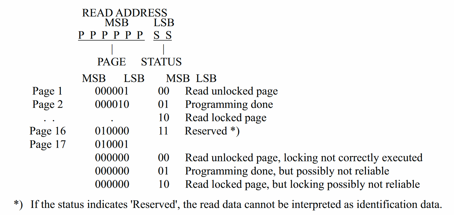
Still, this doesn’t explain why the first three pages return identical data, and what’s with the rest of them pages is unknown too. Back to google it is, then.
Further searches revealed another datasheet, this time it’s TI document SWRS083A for TMS37157. Now this one shows a somewhat similar picture:
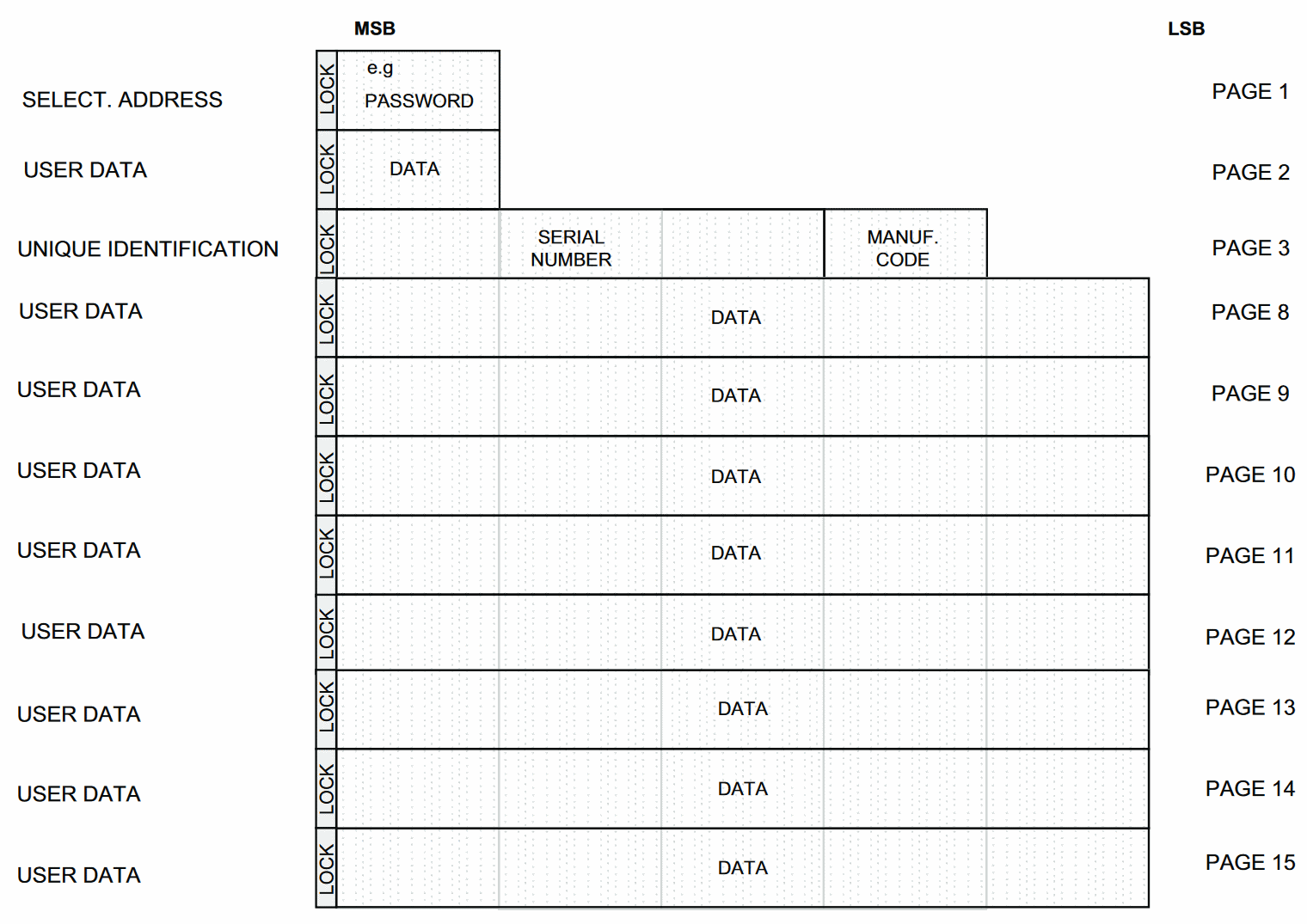
Also the text after it is informative:
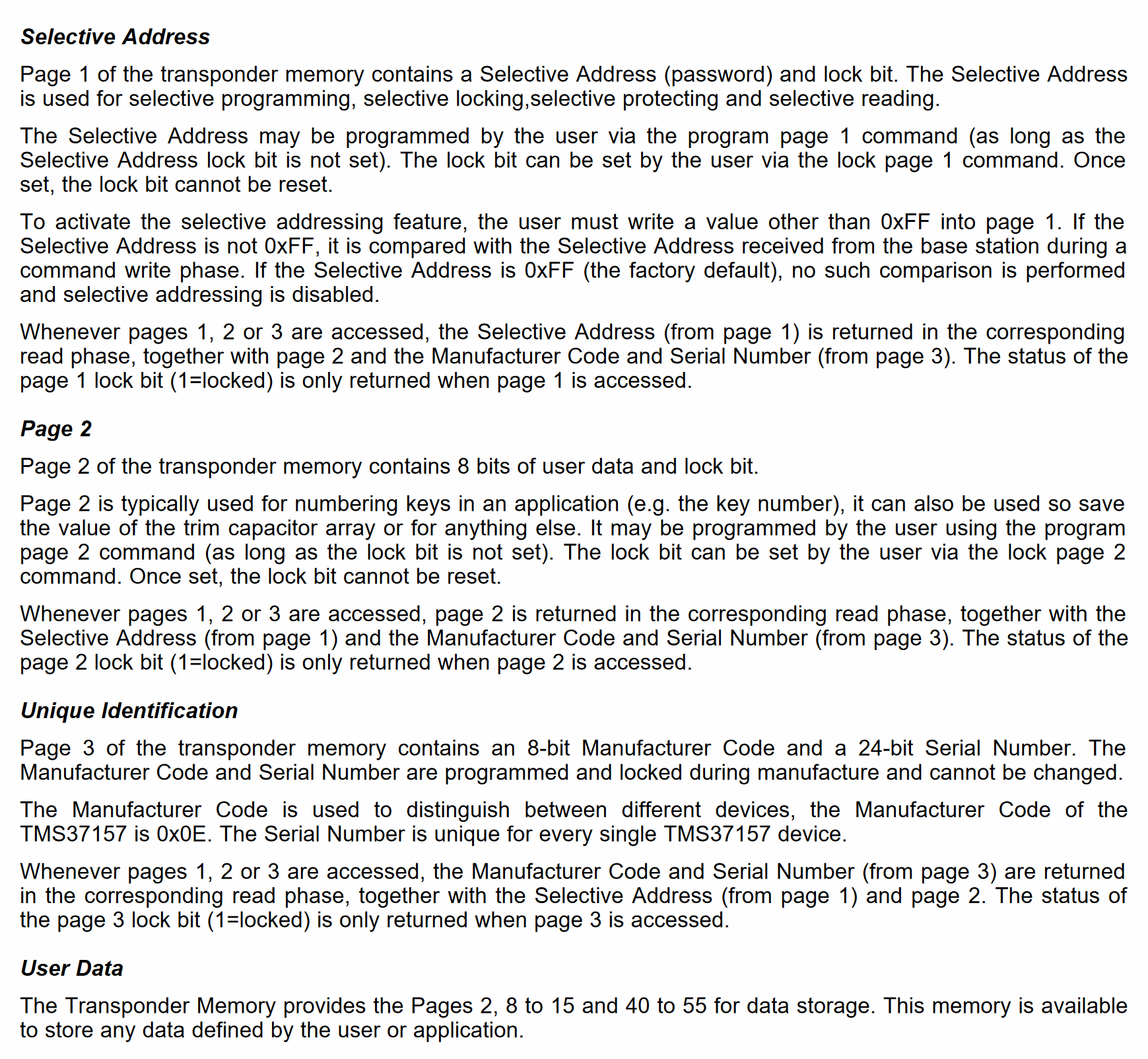
Well, that would explain what’s going on with the first three pages. Pages 7 through 15 seem to conform to what they describe as “user data”. Not immediately apparent is page 18 contents and the exactformat of page 30. In fact, these are not described in this document at all. Baby steps, I guess.
Ze end
With that, I can read both fixed-code and DST-type transponders! That’s a big deal; I started with nothing and now I have something. But there are still things to be done and kinks to be explored: programming memory, and especially running the auth algorithm. I leave this for the next installment though.
Until then, love-peace-melon-bread!