Siemens M1327A3, part 5: TFF chain 2
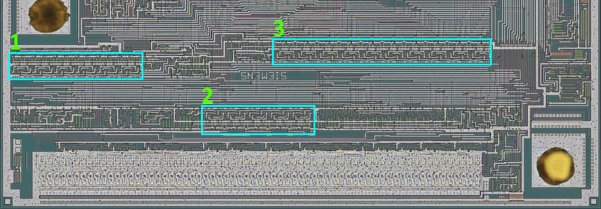
Ahoy sailor, today I shall continue the exploits against Siemens M1327A3. In this post, I will look at the three counter chains I mentioned in the previous part. Here is where they are located on the die:

Chain 1 was discussed previously. Without further blab, let’s get started with chain 2. This one looks simpler, so the analysis will be shorter.
Chain 2
This chain has 5 T flip-flop (TFF) sections plus some more circuitry around them; one is directly below and to the right (red) and connected to the outputs and the other is to the left (yellow). Very similar to what we had before.

By now it should be easy to see what’s going on in the red parts; there is a bunch of transistors stacked in series plus an inverter. Note the VDD is at the bottom this time.

It’s an AND gate with 6 inputs – 5 Q’s and X1. Easy enough. Now to the control part.

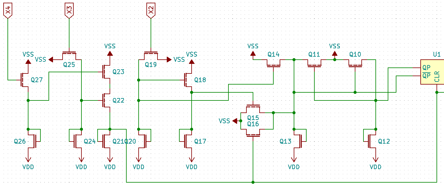
And here is the locations of the transistors in the control part:

It’s very nice that I marked them down, because – of course – I made a mistake when drawing the schematic up: Q15/Q16 should drive QP, not !QP. The marking helped find the mistake.
I’ve moved the parts around and this is what I got:

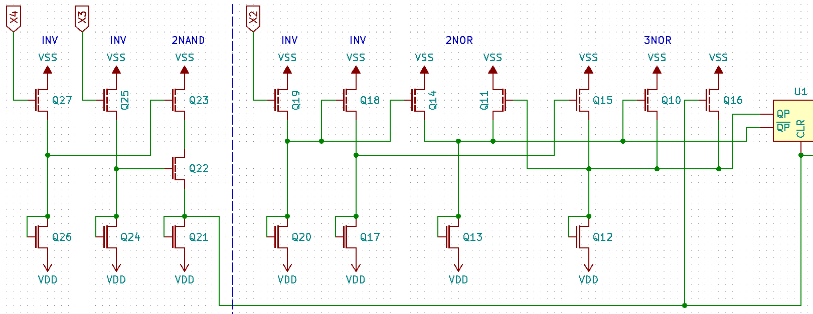
Redrawing this using logic gate symbols:

The right part is a familiar arrangement already encountered previously; its analysis is exactly the same and won’t be done again. One minor difference is that the clock is inverted here. So X2 is in fact !CLK. The counter clear part on the left simply ORs the two inputs: !(!X3 & !X4) = (X3 + X4). They could’ve shaved one inverter off, really. Here is the final schematic for this block:

Other than that, there is nothing too special to this counter. It counts from zero to 11111bin (31dec), outputs a pulse when it reaches that count, and repeats the cycle. Interestingly, no effort was taken to shape the pulse.
Another small puzzle piece in the huge pile took shape.
Until next time!
/DJ